Product Inquiry
Please leave your details and product requirements.

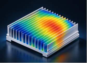
At Zerode, performance is engineered before it is manufactured. Using advanced CFD and FEA thermal simulation, we model airflow, temperature distribution, and thermal resistance across every fin design — identifying hotspots and optimizing geometry before a single unit is produced. This accelerates development, reduces costly prototyping, and ensures every heatsink is thermally optimized for real-world conditions, with results continuously validated against physical testing.
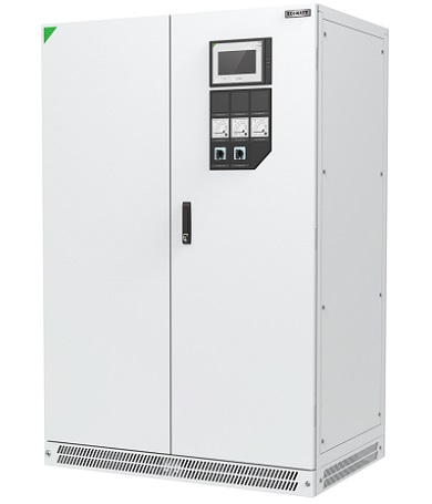
Constrained by product space, the space allocated for this assembly has been defined, with further miniaturization preferred if feasible.
Optimize on the customer’s original heat sink design. Under the premise of reducing costs and shrinking the heatsink footprint as much as possible, the maximum temperature of the heat sink shall not exceed 90 °C at an ambient temperature of 25 °C.
A 3D model of the inverter heatdissipation unit is built via CFD to simulate air flow and heat transfer. Combined with the duct impedance curve, the PQ curves of several axial fans are analyzed to select the most suitable axialflow fan. Parametric optimization and analysis are performed on heatsink structural parameters including fin thickness, height, pitch and fin quantity.
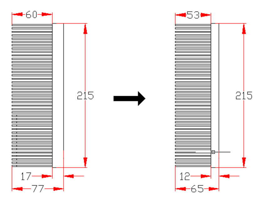
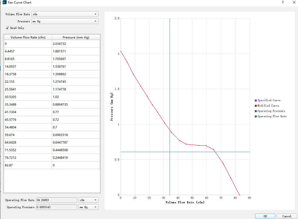
Heatpipe schemes are also compared. Fan selection verification is conducted to finalize the optimal solution.
At an ambient temperature of 25 °C, the maximum surface temperature of the optimized heat sink reaches approximately 83.3 °C, with a temperature rise of 58.3°C. This meets the design requirement that the heatsink surface temperature shall be below 90 °C, leaving a temperature margin of around 6.7 °C. The most appropriate axialflow fan is selected.
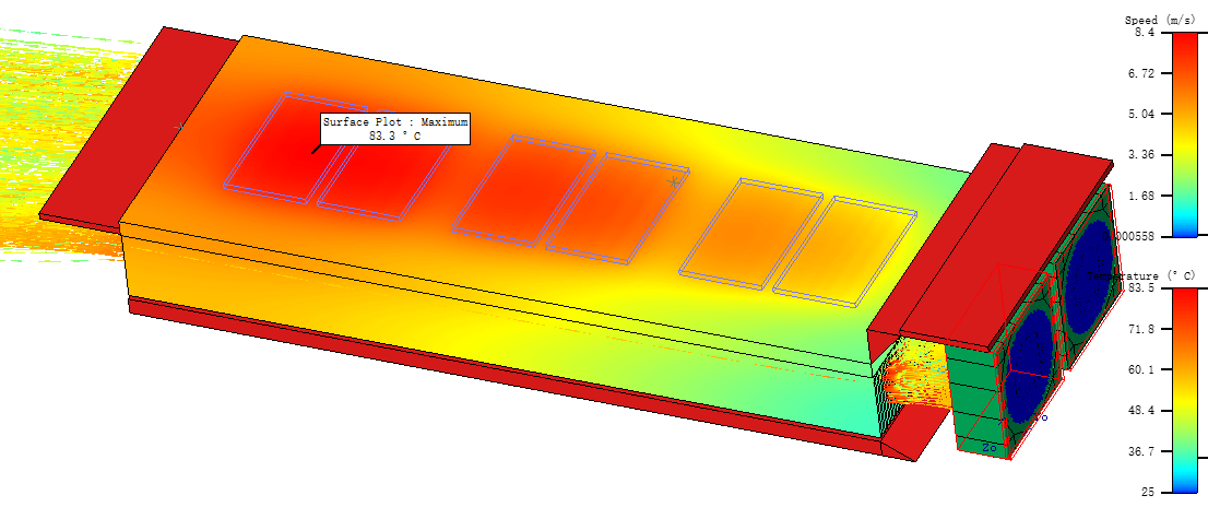
After massproduction, thermal tests were performed on real prototypes under identical working conditions as simulation (ambient temperature 25 °C, same fan and power loss). The measured maximum temperature, temperature rise and fan operating point are well consistent with CFD simulation predictions. The deviation between simulation and test falls within acceptable engineering tolerance. It verifies the rationality of simulation model, boundary conditions and duct parameters. The CFD simulation results are reliable and can support the massproduction design of this product.
The measured maximum temperature reaches 81.8 °C versus the simulated value of 83.3 °C, yielding a temperature deviation of merely 1.5 °C, which is within acceptable engineering tolerance.